Implementation and wiring
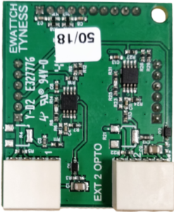
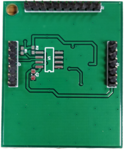
Optic board :


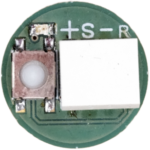
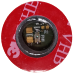
Optic sensor :


Board setup :
The Tyness and the board must be disconnected.
The board must be inserted carefully and with precision of connectors on the locations EXT.1 and/or EXT.2 of the Tyness.
The wires of the OPTIC-SENSOR must be inserted carefully into the terminal blocks.
Setup of the optical sensor :
The light pulse sensor is supplied with a cable of around 80 cm.
The sensor must be centered carefully in front of the light source to be read and attached with the original double-sided sticker. The filter positioned in front of the sensor enables it to limit the influences of the external light intakes.
Special precautions:
If the light source is covered with a transparent plate of the type “Plexiglas”, it is necessary to perform a preliminary test to validate that the light pulses are effectively counted (use of the push-button on the back of the sensor).
In certain conditions, the sensors may be disrupted by external light sources.
We recommend that you be particularly vigilant with the activations/deactivations of the light of the premises, the intakes of external light and artificial lights “scintillating” like neon tubes.
In case of disruptions from external sources, it is necessary to try to camouflage the zones of entry of light (in the window in “Plexiglas”, for example) with an opaque adhesive.
List of counters tested :
The counters appearing in the list below gave satisfaction in our standard test conditions.
Converting pulses to energy :
LED of electricity meters are associated with a weight written on the meters.
Warning : current transformation ratio (TC) and more rarely the voltage transformation ratio (VT) of a meter may have to be added to the weight.
The formula for computing the weight then becomes:
one blink = weight written on the meter x TC x VT
