Installation et mise en œuvre
Positioning of the product
The product must be positioned in a way that does not make it difficult to operate disconnector devices.
The product must be installed in an indoor environment.
Mounting on DIN rail
The product must be installed on a 35mm DIN rail fixed in an electrical panel.
Be careful to lock the housing on the DIN rail.
The product can be removed from the DIN rail by manipulating the movable latch with a screwdriver like any other bracket of the same type.
Installation
Before starting the installation of the SQUID Pro, ensure that you use a 24VDC – 0.5A power supply positioned at the head to power the device. It is important to maintain and separate the wiring of Low Voltage Safety Circuits (TBTS) from the circuits under dangerous voltage to ensure safety and proper system operation.
When wiring, make sure to observe the polarity of the power connector of the SQUID Pro.
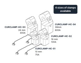
The connection of the measurement clamps to the SQUID Pro is simplified using a quick connector, eliminating the need for tools. Connect the measurement probes to the 12 connectors located on the top and bottom of the device. Make sure not to exceed the maximum current specification for each measurement clamp to avoid the risk of damage or overheating.
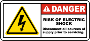
To ensure safety during the installation of the clamps, it is imperative to perform this operation when the circuit is de-energized. Use exclusively Ewattch measurement clamps with the reference CURCLAMP-HC-SX, specially designed for optimal compatibility with the SQUID Pro.
The current measurement clamps of the SQUID Pro have a specific orientation, which must be respected. The clamps must be installed so that the arrow on the clamp points towards the energy consumer.
By following these installation and implementation recommendations, you will ensure safe and efficient operation of your SQUID Pro electrical sub-metering system.
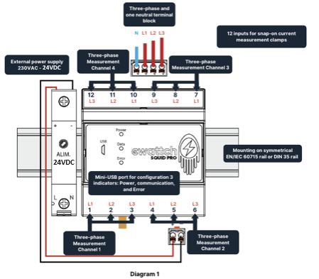
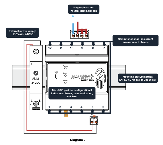
There are 2 possible wiring modes with the SQUID Pro:
- Three-phase mode, allowing the measurement of 4 three-phase circuits.
Caution: It is necessary to follow the indications presented in diagram 1 for the wiring.
- Single-phase mode, allowing the measurement of 12 single-phase circuits.
Caution: It is necessary to follow the indications presented in diagram 2 for the wiring.
Three-phase wiring

Single-phase Wiring


