Additional board TYNESS-OPT-MBUS
1.Hazards and Warnings
Manufacturer is not responsible for user’s failure to comply with the instructions contained in this manual.
Any service performed on this product must be completed by a qualified individual.
Replacement of this product must be performed by a qualified individual.
Failure to use this equipment in accordance with the specifications in this documentation could lead to a hazard.
No parts in this device should be replaced or removed.
Disconnect all power supplies before servicing the equipment.
Terms of use
This board must exclusively be used with a Tyness product from the company
Ewattch.
In the contrasting case, the company Ewattch shall not be held responsible
for any deterioration of the equipment.
2.Presentation
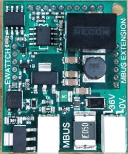
As the Tyness enables a wireless connection in LoRa mode to a data concentrator, the TYNESS-OPT-MBUS board was designed to read counters located near the Tyness.
The M-Bus protocol is a standardized protocol according to the European standard EN 13757. A number of M-Bus slaves were tested and validated by Ewattch (see section “Implementation“).
3.References
TYNESS-OPT-MBUS
Additional M-BUS Board enabling to read field M-Bus sensors (M-Bus slaves) counters of calories, water, and electrical energy.
Comprises a power supply 230 V AC – 36 V DC for the TYNESS ENERGY and TYNESS MODULAR Ewattch which is necessary for the functioning of the MBUS.
4.Usage
The board can be set up on:
- the TYNESS ENERGY (1 location)
- the TYNESS MODULAR (2 locations).
The board comprises two terminal blocks of type WAGO series 20599.
One terminal block for the M-Bus connection cable (a standard telephone cable – jYStY Nx2x0.8 mm – is perfectly adapted) and one for the power supply.
The serigraphy of the printed circuit board specifies the function of the terminal block and, if necessary, the polarization.
A 36V DC power supply is provided with the board.
This power supply enables to supply the M-Bus and its slaves as well as the Tyness.
The Tyness must therefore not be supplied by another type of power supply (ALIM-RAIL- 5V or TYNESS-ALIM-BLOC-5V).
IT IS IMPERATIVE TO RESPECT THE POLARIZATION OF THE POWE SUPPLY
(input 230 VAC and output 36 VDC as well as + and – of the DC output)
The board is intended to power a maximum of 16 M-Bus « slave weights ».
ATTENTION, an M-BUS slave can have a « slave weight » higher than 1.
We ask you to validate this point with the manufacturer of the M-BUS slaves during the design of your network.
5.Technical specifications
Dimensions:
1 additional standard location for Tyness
Connectors :
- 1 connector type WAGO series 2059 for the bus M-Bus (0.14 to 0.34 mm2- 26 to 22 AWG)
- 1 connector type WAGO series 2059 for the power supply (0.14 to 0.34 mm2- 26 to 22 AWG)
- The connector requires the use of a specific tool to disconnect the wire. (ref.: Wago 206-859)
Number of M-BUS slaves :
16 “slave weights” maximum by board
Supply voltage :
36 V DC (power supply provided with the board)
Protocol :
According to European standard EN 13757
Compatible meters :
Heat meters: heat energy, volume, outlet temperature, inlet température
Water meters: volume
Electricity meters: energy
6.Implementation
Above all, the Tyness and the board must be disconnected.
The board must be installed carefully and with precision of the connectors on the locations EXT.1 and/or EXT.2 of the Tyness.
The M-Bus bus cable of the type standard telephone cable – jYStY Nx2x0.8 mm is connected to the left connector (MBUS marking in serigraphy).
The power supply is connected in the right connector respecting the voltage (DC Output) and the polarity as written on the serigraphy (36V on the left, 0V on the right)
Warning: The bus must not be in short circuit if powered. It could cause damage to the board.
List of the M-Bus slaves tested and validated*
The M-Bus protocol is a standardized protocol according to the European standard EN 13757.
The following M-Bus slaves were tested and validated:
*So that we provide you with the best customer service, if the M-BUS
slave that you wish to read does not appear in our list, do not hesitate to send us a copy so that we can test it in order to add it.
Do not hesitate to contact your usual correspondent at Ewattch who will do the necessary testing with our technical team.
7.Settings
The board is configured with the Configurator software.
Always use the latest version of the Configurator and check that your Tyness has the latest version of the firmware. If necessary, carry out an update.
Step 1
● Click on “Config” of the M-Bus board
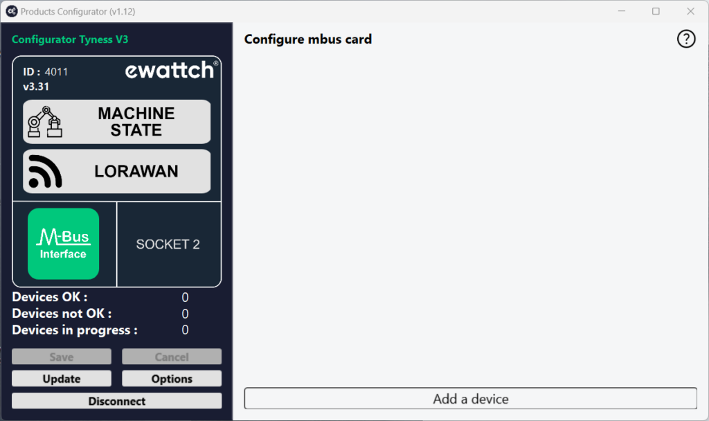
Step 2
● Click on “Add a device” to add an M-Bus slave
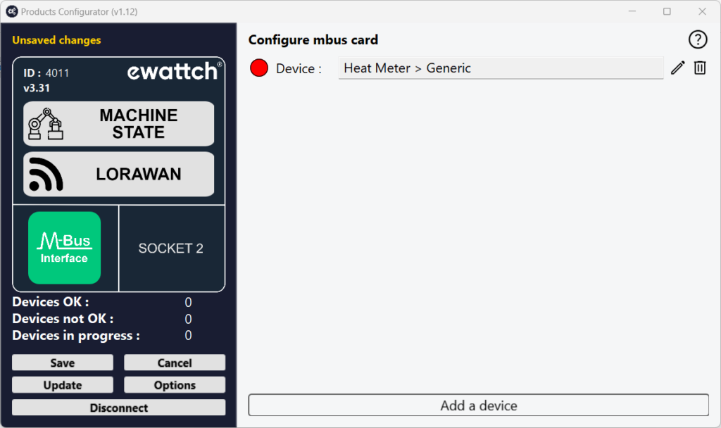
Step 3
● Enter the primary or secondary address of the slave, the baud rate (according to the slave), the period of transmission (periodicity) in minutes (start with 60 then reduce depending on the remaining time), enter the type of slave in the menu Device (heat, water, electricity) and the information to capture.
If secondary addressing is used, you will have to choose a virtual ID for the slave. This ID will be used by the Tyness when radio transmitting data from this slave. Each slave should have a different virtual ID in order to differentiate them.
● Validate by clicking on “ Save“
● Repeat the process for each slave
● When all the slaves are entered, check in the bar graph “Remaining transmission time” that there is still transmission capacity (bar graph completely green = a lot of time, slightly green = a little time remaining).
NB: you can adapt the sending period of the data depending on the bar graph and on your needs. To start the update of the bar graph with a new value of the data sending period, use the “tabulation” key. The value entered is then followed by the unit of time (min)
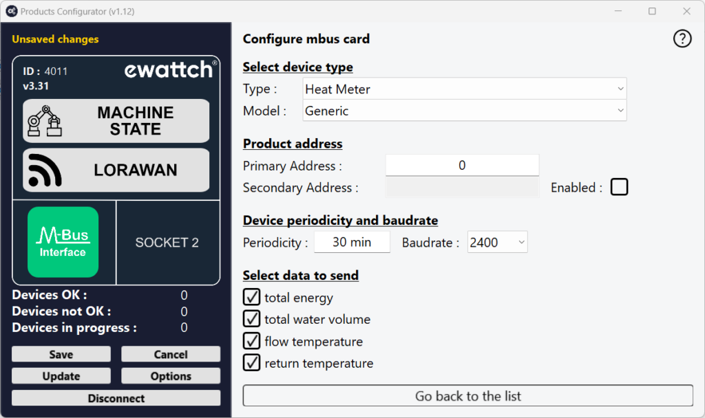
Step 4
● Once all the slaves are entered, validate by clicking on “Save” on the left menu
● If the operation is successful, a window displays “operation successful”.
Validate by clicking on OK.
Your M-Bus board is ready to operate.
M-Bus link status
The color next to each slave indicates the status of the Mbus connection.

Yellow: connection in progress. Please wait for this process to complete.
Green: connection successful and data correctly gathered.
Gray: connection failed, slave could not be reached. It could be caused by an incorrect addressing for example.
Red: connection successful but data could not be recovered. This could be caused by a configuration error (slave configured as electricity meter instead of the specific model of the product).
8.Payload descriptions
A Tyness fitted with an M-BUS board transmits its data in raw format on the different LoRaWAN networks. The section below shows you how to decode the frames (Payload) sent by the Tyness.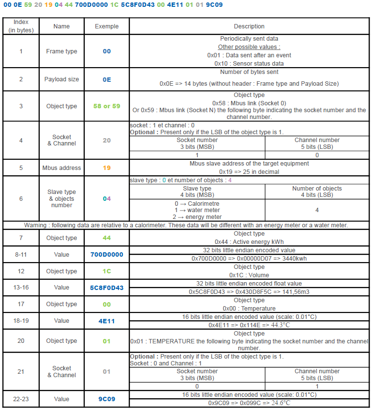
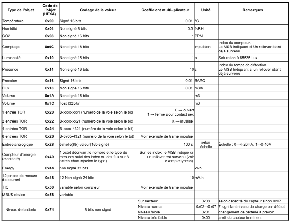
The following table describes the encoding of the data in accordance with the type of object.
Attention, the data will always be transmitted in little endian.
9.Contact

13, Rue Maurice Jeandon
88100 Saint-Dié des Vosges
FRANCE
sales@ewattch.com
+33(0)3.29.57.75.97
www.ewattch.com

