Additional board TYNESS-OPT-OPTIC

1.Hazards and Warnings
Manufacturer is not responsible for user’s failure to comply with the instructions contained in this manual.
Any service performed on this product must be completed by a qualified individual.
Replacement of this product must be performed by a qualified individual.
Failure to use this equipment in accordance with the specifications in this documentation could lead to a hazard.
No parts in this device should be replaced or removed.
Disconnect all power supplies before servicing the equipment.
2.Description and usage
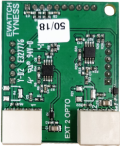
The TYNESS-OPT-OPTIC is an assembly comprised of an additional board containing 2 inputs for recording the light pulses supplied by an LED and a light pulse sensor. The board can be fitted with a second optional sensor with reference OPTIC-SENSOR
The function is used when an energy counter does not have an electrical output (pulse, MBus, Modbus). When an electrical output is available, this is preferred. In general, a cabled electrical transmission will be more precise than the reading of an optical signal.
A list of tested and validated counters is available. For the other counters, a preliminary test is necessary.
A chapter « Setup and cabling » resumes the general principles to follow for the installation of light pulse sensors.
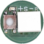
A push-button on the back of the sensor enables to activate a red LED which lights up when the sensor detects a pulse.
The board transmits the index of the pulses of each input at each frame.
The board can be installed on the Tyness Energy (1 location) and the Tyness Modular (2 locations).
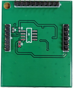
It is comprised of 2 terminal blocks, 4 terminals of type AVX series 9276. The serigraphy of the printed circuit board specifies the function of the terminal block.
The board is powered by the Tyness.
3.Technical specifications
Board
Dimensions :
1 additional standard location for Tyness
Connectors :
2 connectors, 4 terminals type AVX series 9276 (2/10° to 8/10° – 18 to 24 AWG) rigid and flexible multi-strands
Number of inputs :
2 OPTIC-SENNSOR inputs 4 wires
Allocation of the terminal blocks :
Pinout of the terminal blocks :
Sensor
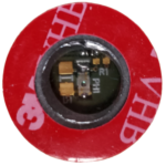
Dimensions :
Diameter 20 mm
Front :
Comprised of the light pulse sensor, a filter limiting light interferences and a double sided opaque self-adhesive foam
Back :
Push-button for activation of the red LED pulse indicator, LED pulse indicator, terminal block 4 terminals of type AVX series 9276 (pinout identical to the terminal block of the board).
4.Implementation and wiring
Optic board :
Optic sensor :
Board setup :
The Tyness and the board must be disconnected.
The board must be inserted carefully and with precision of connectors on the locations EXT.1 and/or EXT.2 of the Tyness.
The wires of the OPTIC-SENSOR must be inserted carefully into the terminal blocks.
Setup of the optical sensor :
The light pulse sensor is supplied with a cable of around 80 cm.
The sensor must be centered carefully in front of the light source to be read and attached with the original double-sided sticker. The filter positioned in front of the sensor enables it to limit the influences of the external light intakes.
Special precautions:
If the light source is covered with a transparent plate of the type “Plexiglas”, it is necessary to perform a preliminary test to validate that the light pulses are effectively counted (use of the push-button on the back of the sensor).
In certain conditions, the sensors may be disrupted by external light sources.
We recommend that you be particularly vigilant with the activations/deactivations of the light of the premises, the intakes of external light and artificial lights “scintillating” like neon tubes.
In case of disruptions from external sources, it is necessary to try to camouflage the zones of entry of light (in the window in “Plexiglas”, for example) with an opaque adhesive.
List of counters tested :
The counters appearing in the list below gave satisfaction in our standard test conditions.
Converting pulses to energy :
LED of electricity meters are associated with a weight written on the meters.
Warning : current transformation ratio (TC) and more rarely the voltage transformation ratio (VT) of a meter may have to be added to the weight.
The formula for computing the weight then becomes:
one blink = weight written on the meter x TC x VT
5.Card settings
The board is configured with the Tyness Configurator software.
Always use the latest version of the Tyness Configurator and validate that your
Tyness has the latest version of the firmware. If necessary, carry out an update.
Step 1
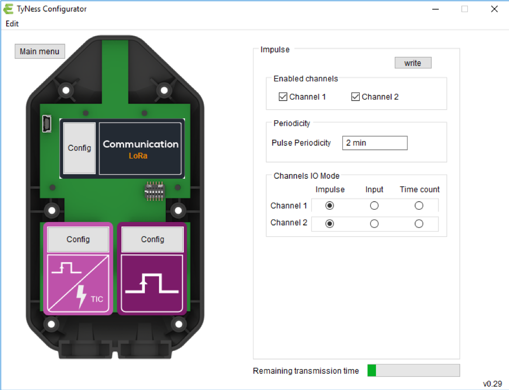
- Click on “Config ” of the TYNESS-OPT-OPTIC board (here on the right)
- Define which inputs will be active (Enabled channels square – click on Channel 1 and/or Channel 2)
- Define the period of sending of the readings (periodicity square)
- Define the functioning mode of each input.
Impulse : returns the index of the number of pulses during the chosen
period.
Input : not usable (the board only detects descending fronts of light).
Time count : non-functional. - Verify in the bar graph “Remaining transmission time” that there remains transmission capacity (bar graph completely green = a lot of time, slightly green = a little time remaining).
NB : you can adapt the period of sending the data in accordance with the bar
graph and your requirements. To start the update of the bar graph with a new
value period of sending the data, use the key “tabulation”. The value entered
is then followed by the unit of time (min)
Once all the values are entered, validate by clicking on “Write”
If the operation has succeeded, a window displays “operation successful”.
Validate by clicking on OK.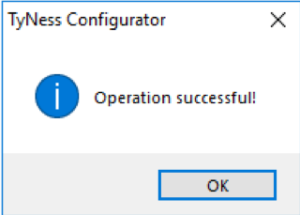 Your TYNESS-OPT-OPTIC board is ready to operate.
By hovering over the board with your mouse, contextual windows display and
enable you to directly read the index of pulses read.
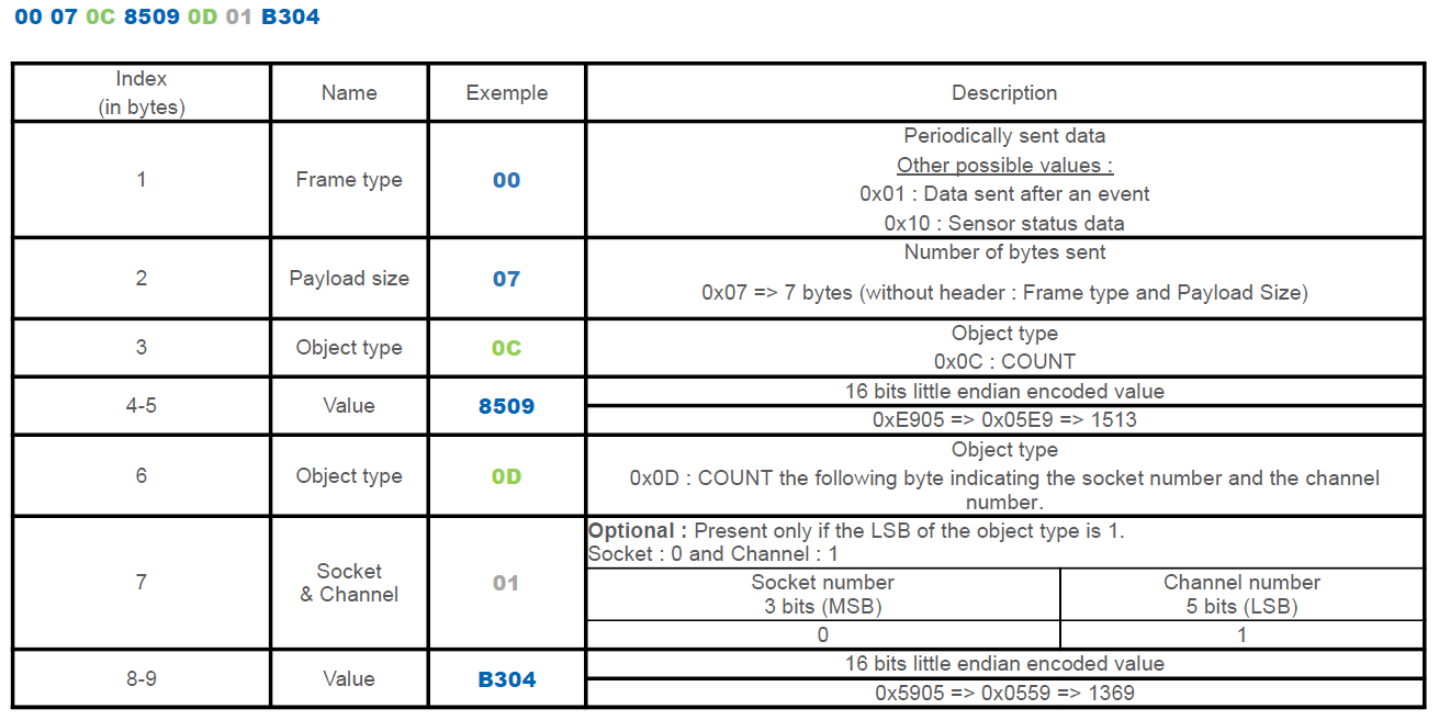
6.Payload descriptions
A Tyness fitted with a OPTIC board transmits its data in a raw format on the different LoRaWAN networks. The section below shows you how to decode the frames (Payload) sent by the Tyness.
7.Contact

13, Rue Maurice Jeandon
88100 Saint-Dié des Vosges
FRANCE
sales@ewattch.com
+33(0)3.29.57.75.97
www.ewattch.com