Additional board Temperature

1.Hazards and Warnings
Manufacturer is not responsible for user’s failure to comply with the instructions contained in this manual.
Any service performed on this product must be completed by a qualified individual.
Replacement of this product must be performed by a qualified individual.
Failure to use this equipment in accordance with the specifications in this documentation could lead to a hazard.
No parts in this device should be replaced or removed.
Disconnect all power supplies before servicing the equipment.
Terms of use
This board must exclusively be used with a Tyness product from the company Ewattch.
In the contrasting case, the company Ewattch shall not be held responsible for any deterioration of the equipment.
2.Description and usage
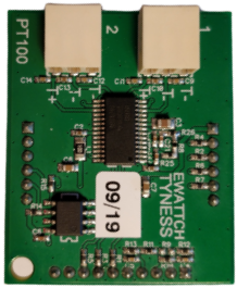
TYNESS-OPT-PT100 and TYNESS-OPT-PT1000 boards are additional boards comprising 4 temperature measurement inputs using 3-wire probes.
The board is intended to be set up on our TYNESS sensors (ENERGY and MODULAR).
It comprises 4 terminal blocks of type AVX series 9276, 3 terminals.
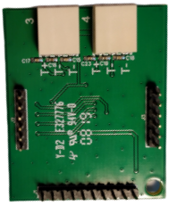
The serigraphy of the printed circuit board specifies the function of the terminal block.
At each transmission, the Tyness returns the instantaneous values of each input.
The board is powered by the Tyness.
Note: reading correction factors cannot be configured in this board.
Référence :
TYNESS-OPT-PT100
TYNESS-OPT-PT1000
SONDE-PT100_3M : PT100 probe Ø 4mm with a cable length of 3m
SONDE-PT100_4M : PT100 probe Ø 4mm with a cable length of 4m
SONDE-PT100_6M : PT100 probe Ø 4mm with a cable length of 6m
SONDE-PT100_10M : PT100 probe Ø 4mm with a cable length of 10m
SONDE-PT100_20M : PT100 probe Ø 4mm with a cable length of 20m
3.Technical specifications
Dimensions:
1 additional standard location for Tyness
Connectors:
4 connectors type AVX série 9276, 3 terminals
(2/10° à 8/10° – 24 à 18 AWG)
● resolution: 0.01°C
● accuracy: +-0.5°C
● measures: -100°C to +300°C
Number of inputs:
4 PT100 or PT1000 inputs 3 wires
Power supply:
By the TYNESS
Allocation of the terminal blocks:
Pinout of the terminal blocks:
4.Implementation
First and foremost, the Tyness and the board must be disconnected.
The board must be inserted on the connectors on the locations EXT.1 and/or EXT.2 of the Tyness.
The wires of the probes must be inserted into the terminal blocks.
In the case of an extension of the cable of the probes, we recommend the use of a shielded cable of type SYT1 and AWG20 between the “field” connection terminal block and the “board” terminal blocks.
5.Settings
The board is configured with the Tyness Configurator software.
Always use the latest version of the Tyness Configurator and check that your Tyness has the latest version of the firmware. If necessary, carry out an update.
Configuration steps
1 – Click on “Config” of the board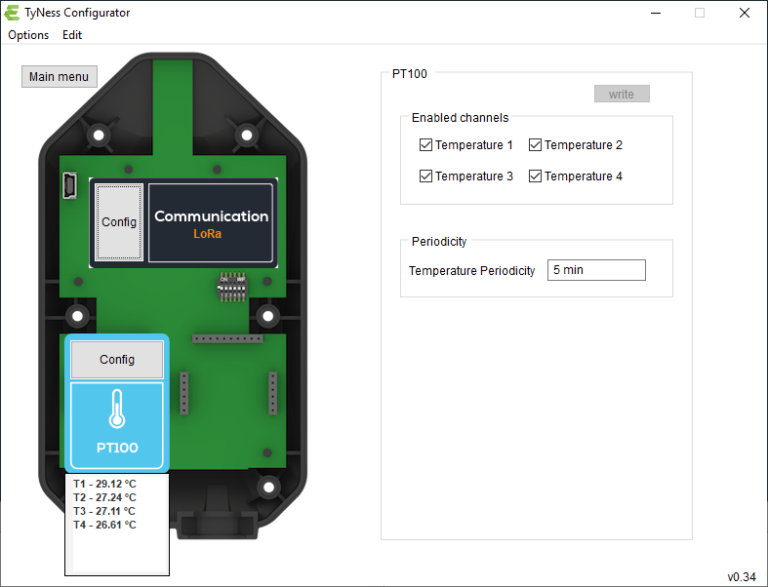
2 – In the insert “Enabled channels”, define which inputs will be active.
To do so, select:
“Temperature 1” and/or “Temperature 2” and/or “Temperature 3” and/or “Temperature 4”
3 – Define the period of sending of the readings: “Temperature periodicity”
4 – Once all the values are entered, validate by clicking on “Write” If the operation is successful, a window displays “operation successful”.
Validate by clicking on OK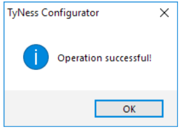
Your board is ready to operate.
Verification of the readings
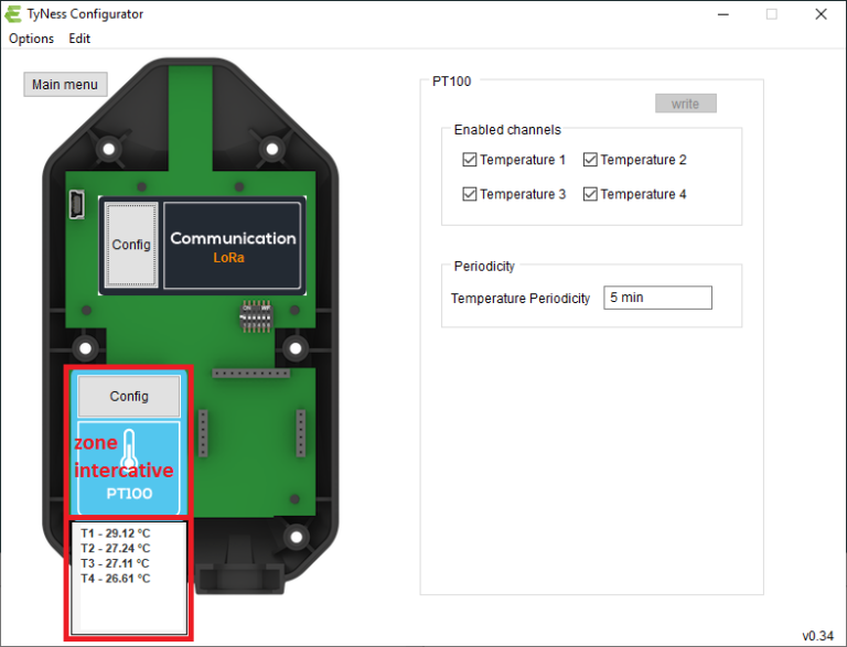
It is possible to display the values of the readings by placing the mouse cursor on the image of the board.
6.Payload descriptions
A Tyness fitted with a temperature measurement board transmits its data in a raw format on the different LoRaWAN networks. The section below shows you how to decode the frames (Payload) sent by the Tyness.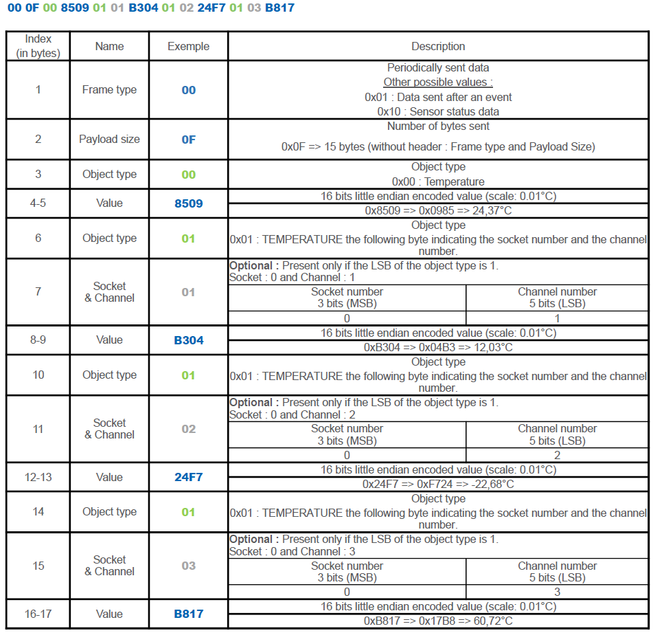
7.Contact

13, Rue Maurice Jeandon
88100 Saint-Dié des Vosges
FRANCE
sales@ewattch.com
+33(0)3.29.57.75.97
www.ewattch.com