Additional board TYNESS-OPT-ANA

1.Hazards and Warnings
Manufacturer is not responsible for user’s failure to comply with the instructions contained in this manual.
Any service performed on this product must be completed by a qualified individual.
Replacement of this product must be performed by a qualified individual.
Failure to use this equipment in accordance with the specifications in this documentation could lead to a hazard.
No parts in this device should be replaced or removed.
Disconnect all power supplies before servicing the equipment.
Terms of use
This board must exclusively be used with a Tyness product from the company Ewattch.
In the contrasting case, the company Ewattch shall not be held responsible for any deterioration of the equipment.
2.Description and usage
REFERENCE: TYNESS-OPT-ANA
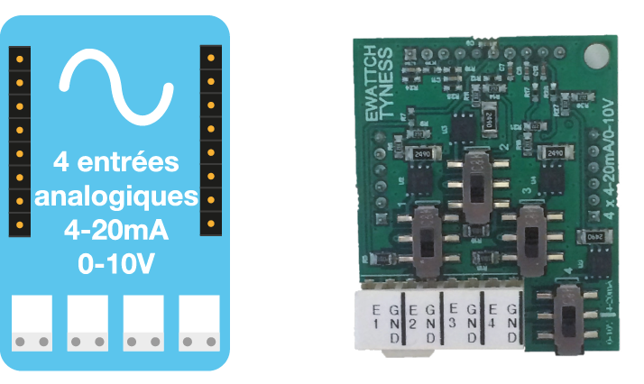
The TYNESS-OPT-ANA board is an additional board comprising 4 analog inputs configurable in 0-10V and 4-20 mA with common mass.
It enables to read the information coming from any sensor with an analog 0-10V and/or 4-20 mA output.
For example: an automaton, a speed variator, a flow-meter, etc.
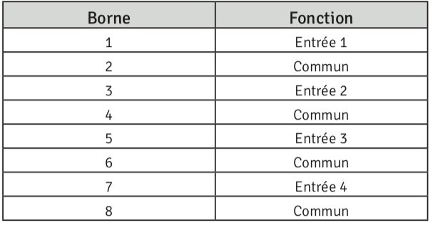
The board is intended to be set up on our TYNESS sensors (ENERGY and MODULAR). It is comprised of one terminal block, 8 terminals, of type AVX series 9276.
A label on the terminal block specifies the function of each terminal (see pinout).
Each input is individually configurable in 0-10V or in 4-20mA using a switch.
At each transmission, the Tyness returns the instantaneous values of each input.
The board is powered by the Tyness.
To supply a sensor by its 4-20mA output (for example, a pyrometer), it is necessary to add a power supply between the board and the sensor.
This point will be detailed subsequently.
3.Technical specifications
Dimensions:
1 additional standard location for Tyness
Connectors:
● 1 connector
● 8 terminals type AVX series 9276 (2/10° to 8/10° – 24 to 18 AWG)
● Rigid and flexible multi-strands
Number of inputs:
4 individually configurable inputs in 0-10V or 4-20mA with common mass in all of the Tyness.
Range of upstream signals:
Input 4-20 mA:
● <1 mA: signal lost from
● from1 mA to 20.5 mA: upstream signal
● >20.5 mA: out of range
● resolution 0.02 mA
● precision +- 100 uA
Input 0-10 V:
● from 0 V to 10.5 V: upstream signal
● >10.5 V: out of range
● resolution 10 mV
● precision +- 50 mV
Power supply:
By the TYNESS
Pinout of terminal block board:
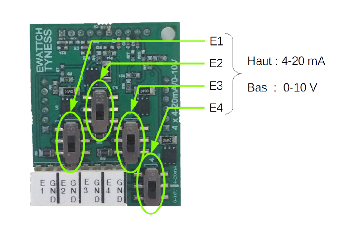
Configuration of the inputs by the switches:
4.Implementation
Before any manipulation, the Tyness and the board must be disconnected.
The board must be installed on the connectors on the locations EXT.1 and/or EXT.2 of the Tyness.
The wires must be inserted into the terminals.
We recommend the use of a cable of type SYT1 AWG20 shielded between the connection terminal block of the cables of the sensors and the connectors of the board.
The inputs must be configured via the switch in 0-10V (switch in low position) or in 4-20 mA (switch in high position).
A serigraphy in the bottom right corner of the board gives a reminder of the configuration of the switches. The far left switch corresponds to input 1, the second to input 2, etc.
5.Settings
The board is configured with the Tyness Configurator software.
Always use the latest version of the Tyness Configurator and check that your Tyness has the latest version of the firmware. If necessary, carry out an update.
Configuration steps
1 – Click on “Config” of the board 4-20mA / 0-10V
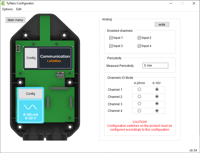
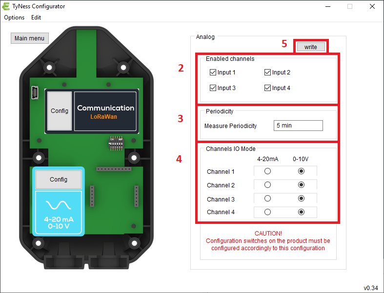
2 – In the insert “Enabled channels”, define which inputs will be active. To do so, select:
“Input 1” and/or “Input 2” and/or “Input 3” and/ or “Input 4”
3 – Define the period of sending of the readings: “Measure periodicity”
4 – Define the type of input (4-20mA or 0-10V) for each input.
ATTENTION: the configuration on the Tyness confiscator must correspond to the physical configuration of the switches on the board!
5 – Once all the values are entered, validate by clicking on “Write” If the operation has succeeded, a window displays “operation successful”.
Validate by clicking on OK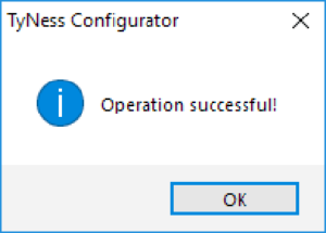
Your TYNESS-OPT-ANA board is ready to operate.
Verification of the readings
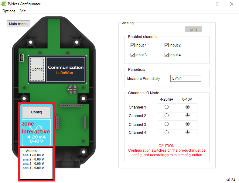
It is possible to display the values of the readings by placing the mouse cursor on the image of the analog board.
6.Sensor supply
Certain sensors are powered by the data loop.
In this case, a power supply must be integrated into the loop according to the following diagram where the receptor corresponds to the TYNESS-
OPT-ANA board and the Transmitter corresponds to the sensor read.
The 0V of the power supply must compulsorily be connected to the common mass of the board.
Reminder: the common masses of the 4 inputs and of the Tyness are interconnected.
An error of polarization may damage the Tyness and its power supply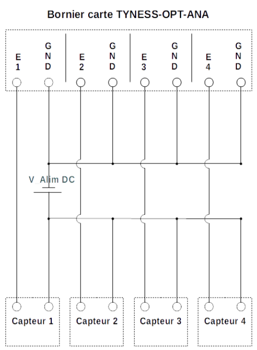
7.Payload descriptions
A Tyness fitted with an ANA board transmits its data in a raw format on the different LoRaWAN networks. The section below shows you how to decode the frames (Payload) sent by the Tyness.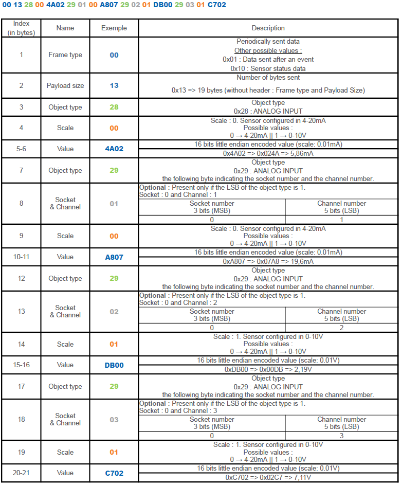
8.Contact

13, Rue Maurice Jeandon
88100 Saint-Dié des Vosges
FRANCE
sales@ewattch.com
+33(0)3.29.57.75.97
www.ewattch.com