Additional board TYNESS-OPT-MODBUS

1.Hazards and Warnings
Manufacturer is not responsible for user’s failure to comply with the instructions contained in this manual.
Any service performed on this product must be completed by a qualified individual.
Replacement of this product must be performed by a qualified individual.
Failure to use this equipment in accordance with the specifications in this documentation could lead to a hazard.
No parts in this device should be replaced or removed.
Disconnect all power supplies before servicing the equipment.
Terms of use
This board must exclusively be used with a Tyness product from the company
Ewattch.
In the contrasting case, the company Ewattch shall not be held responsible
for any deterioration of the equipment.
2.References
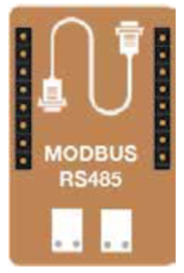
The TYNESS-OPT-MODBUS board is an additional ModBus interface board
enabled to communicate in master or slave mode.
In master mode, it enables to read the data of one or more sensors
communicating in ModBus so as to copy the Modbus tables to the internal
tables of the Tyness.
In slave mode, it is integrated into a ModBus network and provides the
master of the network with an internal table in the Tyness.
3.Description and usage
The board can be set up on:
● the TYNESS MODULAR sensors (2 locations)
The board functions in communication mode ModBus RTU RS485. The
transmission speed is configurable from 1200 to 57600 bauds.
It is comprised of one terminal block 3 terminals of type AVX series 9276.
The serigraphy on the angle of the printed circuit board specifies the role of
each terminal.
Ewattch solutions facilitate simplicity in the user experience. We have simplified the integration of the ModBus function in the system with, for example, the USB configuration tool and an auto-configuration system for compatible sensors.
4.Technical specifications
Dimensions:
1 additional standard location for Tyness
Connectors:
1 connector, 3 terminals, type AVX series 9276
(2/10° to 8/10° – 18 to 24 AWG) rigid and flexible multi-strands
Number of M-BUS slaves:
15 slave maximum
Radio data:
40 bytes per radio transmission
5.Implementation and wiring
Pinout of the terminal block:
Configuration with the:
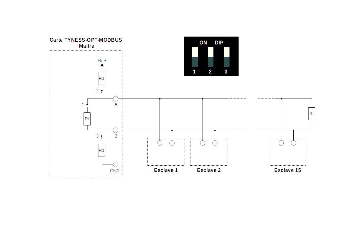
The resistances of polarization Pull Up and Pull Down must only be installed in a single place of the Bus, usually at the level of the master.
In this case, move switches 2 and 3 to the position “ON” (high position).
The resistances of line termination are to be installed at each extremity of the bus, which is usually on the furthest away master and slave.
In this case, move switch 1 to the position “ON” (top position).
Bus RS485 :
We remind you that the RS485 bus is defined by the standard EIA-TIA-485-A and the application guide TSB-89-A.
It is recommended to use a shielded twisted pair (general shielding) of minimum section 0.20 mm2 (AWG 24) of Impedance 120 ohms of type L IYCY-CY.
Configurable transmission speed:
1 200, 2 400, 4 800, 9 600, 19 200, and 57 600 bauds.
We recommend using the speed 9 600 bauds.
Available MODBUS configurations:
- Parity: even, odd or absence of parity
- Number of bits of stop (1 or 2 bits)
- Communication mode: Master or Slavee
6.Functioning in master mode
This mode will be used when you wish to read counters configured in slave mode.
The board issues Modbus requests to read each counter (it is the master on the network, the counters are the slaves) and then radio transmits the data.
Physical configurations
Depending on the topology of the bus, switches 2 and 3 must be in “ON”
mode (high position) in order to put in place the Pull Up and Pull Down and switch 1 in
“ON” mode (high position) if the bus starts at the level of the board and to put
in place the resistance of line termination.
Software configuration for the reading of the slaves
Ewattch provides an USB configuration tool, for quick and easy configuration.
This tool can be downloaded on this website: https://www.ewattch.com/english-documentation/
In order to provide you with the best service, if the slave you wish to read is not on the compatibility list, do not hesitate to send us one so that we can test it.
Contact your usual correspondent who will do the necessary with our technical team.
Requests accepted :
In master mode, the following requests are accepted:
-
- ReadHoldingRegisters 0x03
- ReadInputRegister : 0x04
- WriteMultipleRegisters 0x10
Compatible slaves :
The following table lists the slaves currently integrated with the configuration software. It also indicates the data collected as well as the share of the board configuration memory taken by the addition of a slave. It is for example possible to configure a maximum of 5 slaves if their configuration takes 20% per slave.
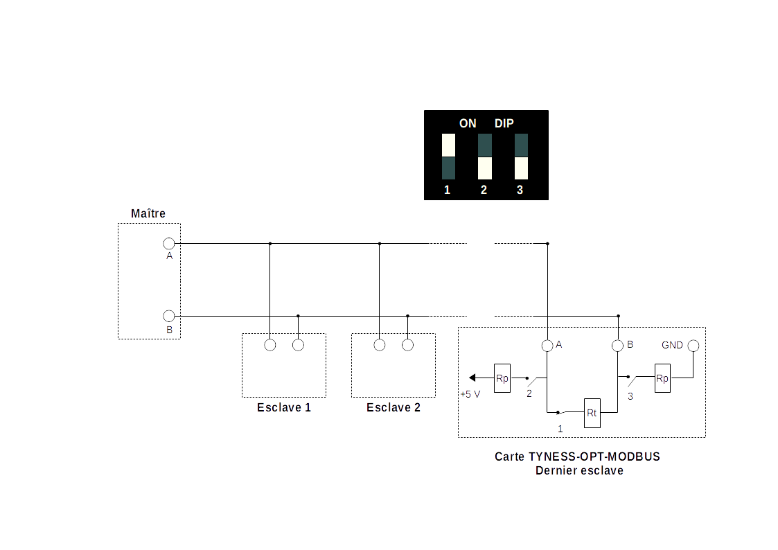
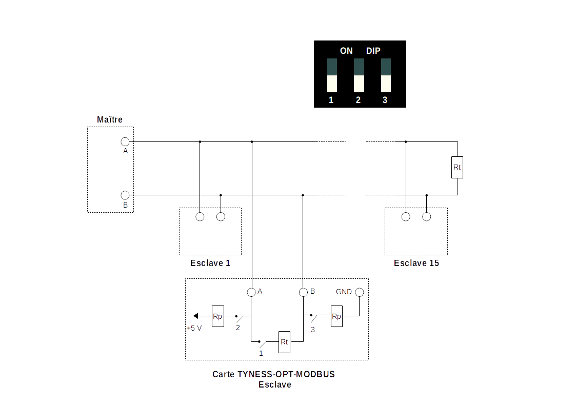
7.Functioning in slave mode
This mode of functioning will be used when you wish, for example, to send back on the network LoRa the data coming from an existing ModBus network.
The master of the ModBus network writes the preferred values in the table of the board.
The table accepts a maximum of 512 words of 16 bits.
All or part of the table may be the subject of a LoRa frame generation.
The frame contains a maximum of 20 words of 16 bits.
Ewattchcloud compatibility
The data can be displayed directly on the Ewattchcloud platform. To do this, the modbus table must respect a format.
An online tool is available here. It makes it possible to obtain the modbus table model to follow according to the necessary data.
Physical configurations
- Switches 2 and 3 must be in “OFF” mode (low position) so as to not setup the Pull Up and Pull Down
- Switch 1 must be in “ON” mode (high position) if the board is the last slave of the bus. In the contrasting case, switch 1 must be in “OFF” mode (low position).
Software configuration for the writing in the table
On the Tyness Configurator, it is necessary to:
- Allocate an address to the board
- Configure the zone(s) of the table authorized in read and/or write (IN, OUT and IN-OUT)
- Configure the LoRa frame generation.
Requests accepted:
In slave mode, the following requests are accepted:
- WriteMultipleRegisters : 0x10
- ReadDiviceIdentification : 0x2B
- ReadHoldingRegisters : 0x03
- ReadInputRegister : 0x04
- ReadExceptionStatus : 0x07
- ReadDiagnostic : 0x08
Compatible masters:
8.Configurations of the board
The board is configured with the Tyness Configurator software.
Always use the latest version of the Tyness Configurator and check that your
Tyness has the latest version of the firmware. If necessary, carry out an update.
Step 1
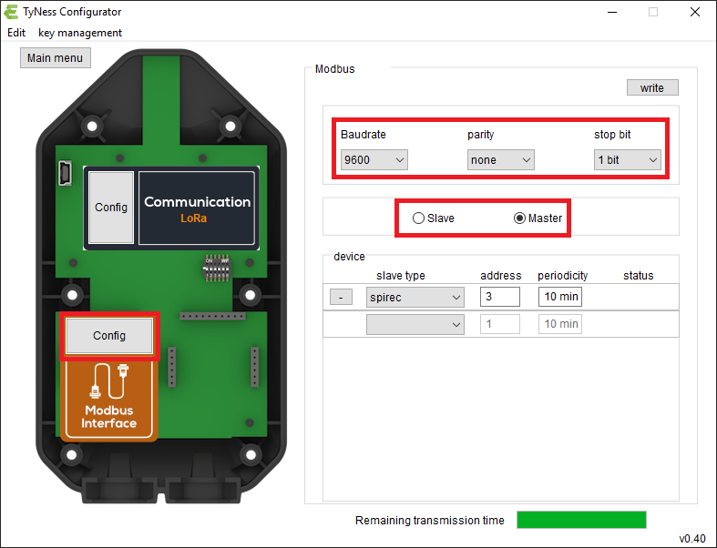
1 – Click on « Config » of the Modbus board
2 – Select the required baudrate, parity and number of stop bits
3 – Select the role of Tyness on the bus. Slave or master.
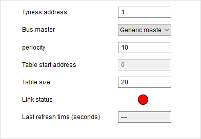
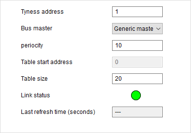
Step 2 Tyness is a slave
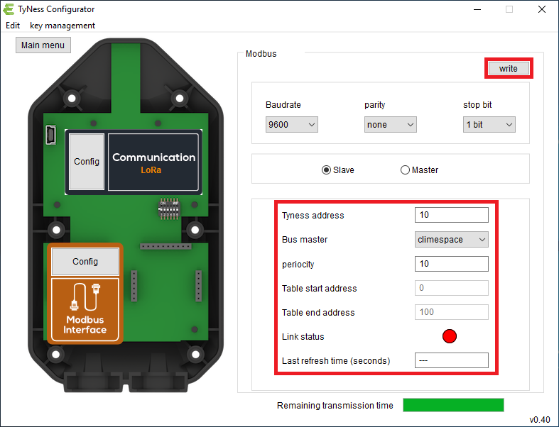
1 – Configure the Modbus address off the Tyness in « Tyness address »
2 – Select the bus master in the compatible masters list « Bus master »
3 – Define the time between two radio transmissions in « periodicity »
4 – Once all the values are entered, validate by clicking on “Write”
Step 3 Tyness is a master
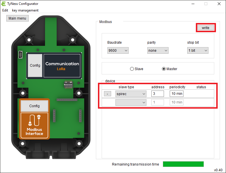
1 – Select the slave(s) to be read from the list of compatible slaves. « slave type » section
2 – Configure the Modbus address (es) of the slaves in the « address » section
3 – Define the time between two radio transmissions in the « periodicity » section
4 – Once all the values are entered, validate by clicking on “Write”
Connection status
The status color gives the state of the connection.
Yellow: connection in progress
![]()
Red: the connection could not be established successfully. This can be caused by a wiring fault, or a configuration fault.
![]()
Green: the connection has been established successfully and the information has been retrieved.
![]()
9.Payload descriptions
The description of the radio exchange format is available upon request.
10.Contact

13, Rue Maurice Jeandon
88100 Saint-Dié des Vosges
FRANCE
sales@ewattch.com
+33(0)3.29.57.75.97
www.ewattch.com